
ESAB industrial welding equipment logo
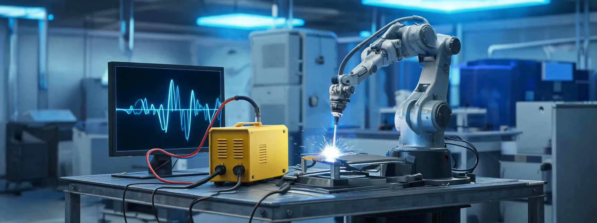
Digital welding power source and waveform engineering station
Arc control and automation

ESAB Technology from Waveform Intent to Cell Evidence

Digital control is valuable when its settings, interfaces and limits can be traced through a representative joint. This page uses the manifest's six-slot roadmap schema only as a layout; every slot addresses welding technology.

Trace the technology path
Control roadmap

Six checkpoints from sensing to production release

A modern interface does not make a procedure self-validating. Each checkpoint pairs digital capability with a physical observation and a documented owner.

  1. 01

    Define

    Material, joint, position and acceptance route.

  2. 02

    Configure

    Process, waveform, feeder, torch and consumable.

  3. 03

    Connect

    Power, work return, I/O and cell safeguards.

  4. 04

    Observe

    Arc behavior, feeding, thermal load and faults.

  5. 05

    Inspect

    Coupon result against stated criteria.

  6. 06

    Release

    Approved range, change control and maintenance.

Feature evidence

Ask what the control changes at the joint

Labels such as synergic, pulsed, adaptive or connected describe control approaches. They do not, by themselves, establish penetration, mechanical properties, defect rate or productivity. A defensible review connects the control to a repeatable setup and a measured outcome.

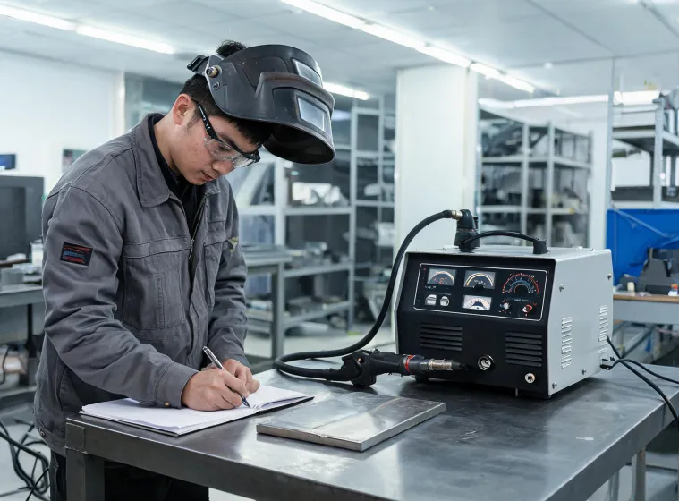
Engineer recording welding parameters during a coupon trial
CONTROL 01

Waveform and arc response

Review how the selected mode manages current transitions, arc length and transfer for the specified wire, gas and joint. Verify starts, stops, tack behavior and positional stability on representative coupons.

Evidence:

Recorded setup, 60-second observation window, restart count and inspected bead.

CONTROL 02

Wire delivery as a system

Drive rolls, liner, gun length, contact tip, spool location and wire condition can dominate feeding stability. A power-source screen cannot diagnose a mechanical restriction that was never recorded.

Evidence:

Feed-path inspection, measured distance, consumable identification and repeat run.

CONTROL 03

Automation communication

Robot and cell integration adds I/O mapping, sequencing, error handling, torch service and safe-state behavior. Nominal cycle time is incomplete without recovery and planned maintenance.

Evidence:

Interface checklist, simulated faults, recovery steps and cell acceptance record.

CONTROL 04

Parameter governance

Saved jobs can support consistency only when permissions, version ownership and change triggers are defined. Uncontrolled recall can repeat an obsolete setup just as consistently as an approved one.

Evidence:

Named owner, revision identifier, approved range and audit trail.

Interface ecosystem

Technology crosses equipment boundaries

The “partners” slot is interpreted as an interface map. It does not imply commercial endorsement or a certified integration.

PWR

Incoming power

Voltage, phase, protection, generator behavior and grounding need confirmation at the installation.

MOT

Motion platform

Robot, cobot, positioner or mechanized carriage must share a defined sequence and safe state.

FUM

Fume control

Extraction design follows process, consumable, enclosure and operator exposure—not a generic airflow label.

QMS

Quality record

Procedure, operator, consumable, settings and inspection result must remain connected.

Verification scorecard

Four records close the technology loop

01Configuration baseline
02Representative coupon
03Inspection outcome
04Release boundary

No universal performance percentage is claimed. Results depend on the specific equipment, joint, operator or automation cell, consumable, environment and acceptance method.

Technology review

Configure the process, test the joint, preserve the evidence

Send the application envelope and control objectives to frame a reproducible ESAB technology discussion.