
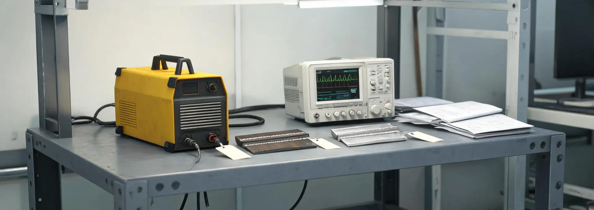
Translate a joint drawing, production target and inspection route into an equipment configuration, trial plan and handover record. The service scope separates what can be checked on a coupon from what must be qualified under the customer's governing code.
Each work package starts with facts that change the process window. Missing inputs are recorded as open items rather than concealed behind a generic recommendation.
Model availability and final suitability still require regional product documentation. The table describes an engineering conversation, not a promise that every service is available in every market.
| Review workstream | Required input and controlled output |
|---|---|
| Process selection | Input: material, thickness, joint, position and deposition objective. Output: reasoned comparison of MIG, TIG, stick or a mixed route, including limitations that remain to be tested. |
| System configuration | Input: incoming power, feeder distance, torch duty, cable reach, gas and consumable plan. Output: configuration checklist covering the power source and the connected system. |
| Coupon protocol | Input: representative joint and acceptance criteria. Output: recorded parameter sheet, consumable lot, test sequence and inspection observations suitable for comparison. |
| Automation interface | Input: cycle target, fixture concept, communication needs and safeguarding boundary. Output: interface questions for robot, positioner, torch, seam tracking and cell controls. |
| Production handoff | Input: approved procedure and operator responsibilities. Output: setup baseline, change-control points, daily checks and escalation conditions. |
The method creates a traceable sequence. It does not substitute for WPS, PQR, welder qualification, code inspection or site safety responsibilities.
Name the defect, throughput constraint or selection decision being investigated. Define the base material specification, thickness, joint geometry, position and acceptance route. If two processes are compared, keep the coupon and evaluation method constant.
Capture power source, feeder, torch, cable lengths, contact parts, wire or electrode class, diameter, gas, polarity and incoming power. For a 60-second stability observation, record interruptions and corrections rather than reporting a subjective “smooth arc.”
Use the planned joint orientation and a realistic thermal sequence. A flat bead on plate cannot validate an out-of-position groove weld. High ambient temperature, drafts, surface contamination and long leads must be reproduced when they are part of the actual operating environment.
Document visual observations and any required macroetch, bend, hardness or nondestructive examination. Equipment settings are evidence only when linked to the coupon, operator, consumable and inspection result.
Identify qualified ranges, prohibited substitutions, maintenance checkpoints and the change conditions that trigger another review. Aluminum feeding routes, pulsed transfer, long cable runs and automated interfaces can each narrow the acceptable configuration.
Send the material, joint, position, output target, power supply and inspection method. The technical discussion can then identify the next verifiable step.